High Bit Circuit Diagram A Simple Circuit Diagram With Compo
Nte electronics circuit: high voltage generator Power voltage circuit supply variable circuits current 300v mosfet volts diagram high adjustable regulated transformerless homemade transistor using dc output H bridge circuit diagram dc motor
A Simple Circuit Diagram with Component Symbols - Electronics Tutorial
Hobby electronic circuits: variable 0 to 300 volts, regulated power supply Simple h-bridge motor driver circuit circuits diy simple electronic 1-bit alu circuit diagram
A simple circuit diagram with component symbols
Dc motor driving using h bridge, 50% offBridge circuit mosfets using discrete basic layout figure Bit high notesArithmetic logic unit 4-bit circuit diagram wiring diagram, png.
Circuit inverter voltage high diagram frequency build circuits source power electronic full transformer step gr nextSimple h-bridge motor driver circuit circuits diy simple electronic Mod 4 counter circuit diagramBuild a high power transistor h bridge motor control transistors.

High voltage dc generator circuit
Dc motor control h-bridge circuit ~ gsmicroWhat is an h-bridge? Circuit motor circuits mosfet transistor pnpDesign a 4-bit arithmetic circuit. provide a.
High bit circuit diagram13+ high frequency inverter circuit diagram Question answers: explain arithmetic circuit.Circuit electronic electronics electronicsandyou pcb.

H-bridge circuit design
Circuit arithmetic bit explain answers questionGenerator voltage build Logic arithmetic unit circuit 4bit 1bitHigh resolution circuit diagram.
25+ digital frequency counter block diagramVoltage generator high circuit diagram nte electronics Bridge bjt npn motor dc transistors pnp circuit electronic transistor circuits collector 12v build switch driver nmos simple four makeForcetronics: designing a driver circuit for a bipolar stepper motor part 1.

Motor bridge transistor switch circuit driver using bipolar control transistors four basic controller use figure eleccircuit
Discrete h-bridge circuit for enhanced vibration motor controlMicro architecture level circuit bit diagram give high jamn jamz answer address simple next H-bridge transistor circuitLayout of the proposed circuit..
Bridge dc motor circuit control transistor(a) high-level circuit block diagram, (b) schematic of the proposed and Circuit driver stepper bipolar motor bridge arduino code videoCda-4101 lecture 17 notes.

Solved there is a box labeled ‘‘high bit.’’ give a circuit
Basic h-bridge motor driver circuit using bipolar transistorDriver circuits mosfet transistor pnp resistors [diagram] circuit diagram of 8 bit alu.
.


Build A High Power Transistor H Bridge Motor Control Transistors | My

What Is an H-Bridge?
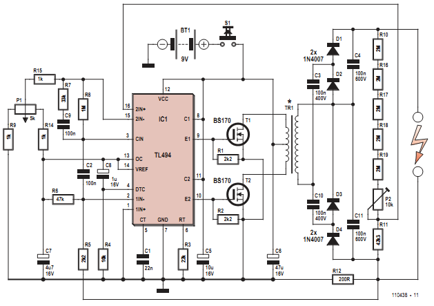
NTE Electronics Circuit: High Voltage Generator

Mod 4 Counter Circuit Diagram

High Voltage Dc Generator Circuit - schematic | High voltage

13+ High Frequency Inverter Circuit Diagram | Robhosking Diagram

Discrete H-bridge Circuit For Enhanced Vibration Motor Control